
NewsDetails
Mechanical Load Testing Methods for Power Fittings
author:Dachuan time:2026-04-17 14:07:28 Click:199
Mechanical Load Testing Methods for Power Fittings
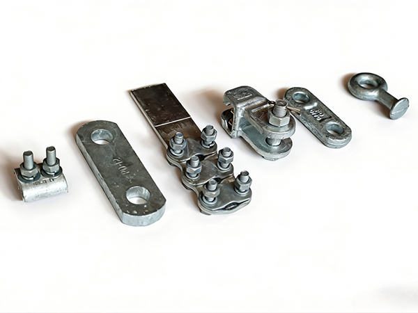
Mechanical load testing is a critical quality assurance process for power fittings used in overhead transmission and distribution systems. These fittings—including clamps, connectors, suspension assemblies, tension hardware, and anchor components—must withstand complex mechanical stresses throughout their service life. Load testing verifies structural integrity, safety margins, and compliance with international standards before field deployment.
1. Purpose of Mechanical Load Testing
Mechanical load testing is performed to:
Verify rated mechanical strength of fittings
Ensure safety under extreme operating conditions
Detect manufacturing defects or material weaknesses
Validate design calculations and simulation results
Confirm compliance with international standards
This testing is essential for preventing in-service failures in high-voltage power systems.
2. Types of Mechanical Loads in Testing
2.1 Tensile Load
Simulates conductor tension and structural pulling forces
Applied along the main axis of fittings
Critical for tension clamps, insulator strings, and anchor hardware
2.2 Compression Load
Simulates squeezing forces in clamping components
Applied in cross arms, brackets, and support fittings
2.3 Shear Load
Simulates lateral forces acting across joints and fasteners
Important for bolts, pins, and clevis connections
2.4 Bending Load
Simulates wind pressure and conductor weight effects
Applied in suspension and support fittings
2.5 Combined Load
Simultaneous application of tension, bending, and shear
Reflects real-world operating conditions more accurately
3. Standard Mechanical Load Testing Methods
3.1 Tensile Strength Test
This is the most common test for power fittings.
Procedure:
The fitting is mounted in a tensile testing machine
Load is applied gradually until rated load or failure
Deformation and breaking load are recorded
Evaluation:
Must exceed specified minimum breaking load (MBL)
No permanent deformation under working load
3.2 Proof Load Test
Applied at a load higher than normal operating load but lower than breaking load
Ensures structural integrity without failure
Often used as acceptance test in production
3.3 Ultimate Load Test
Load is increased until failure occurs
Determines maximum strength capacity
Used for design validation and safety factor verification
3.4 Fatigue Load Test
Simulates long-term cyclic loading conditions
Repeated loading and unloading cycles applied
Evaluates resistance to crack initiation and propagation
3.5 Slip Test (for Clamps)
Measures conductor slippage under tension
Ensures gripping force is sufficient
Critical for tension and suspension clamps
4. Testing Equipment and Setup
4.1 Universal Testing Machine (UTM)
Used for tensile, compression, and bending tests
Provides controlled loading and measurement
4.2 Hydraulic Load Frames
Used for high-capacity fittings and large structural components
Capable of applying multi-ton loads
4.3 Specialized Fixture Systems
Custom grips and fixtures simulate real installation conditions
Ensures accurate load transfer during testing
4.4 Data Acquisition Systems
Records load, displacement, and strain
Provides real-time monitoring of performance
5. Test Conditions and Parameters
5.1 Loading Rate
Must follow standardized gradual increase
Prevents shock loading and inaccurate results
5.2 Temperature Conditions
Tests may be conducted at ambient, high, or low temperatures
Ensures performance in different climates
5.3 Alignment Accuracy
Proper alignment prevents unintended bending stress
Critical for tensile testing accuracy
6. Failure Modes Observed During Testing
6.1 Material Fracture
Occurs when load exceeds ultimate strength
Indicates insufficient material strength or defects
6.2 Plastic Deformation
Permanent bending or distortion after load removal
Indicates insufficient safety factor
6.3 Bolt or Connection Failure
Thread stripping or shear failure
Indicates improper design or poor assembly
6.4 Slippage Failure
Conductor or component slipping under load
Indicates inadequate clamping force
7. Quality Acceptance Criteria
A power fitting is considered acceptable if:
It withstands rated load without failure
No permanent deformation under working load
No visible cracks or damage after proof testing
Meets specified safety factor (typically ≥2.5–3.0)
Passes fatigue and slip resistance tests
8. Relevant International Standards
Mechanical load testing is governed by several key standards:
IEC 61284 – Requirements and tests for overhead line fittings
IEC 60826 – Design criteria for overhead transmission lines
ASTM A370 – Mechanical testing of steel products
ISO 6892 – Tensile testing of metallic materials
IEEE 978 – Guide for testing overhead line hardware
9. Importance of Mechanical Load Testing
Ensures operational safety of power networks
Prevents catastrophic line failures
Extends service life of fittings
Validates design and manufacturing quality
Builds reliability in high-voltage infrastructure
10. Future Trends in Load Testing
Automated digital load testing systems
Real-time strain and fatigue monitoring
AI-based failure prediction models
Simulation-driven testing (digital twin technology)
Higher precision multi-axis load testing systems
11. Conclusion
Mechanical load testing is an indispensable process in ensuring the reliability and safety of power fittings used in transmission and distribution systems. Through tensile, fatigue, slip, and proof load tests, manufacturers can verify that components meet stringent performance requirements. With advancements in testing technology and international standards, load testing continues to play a vital role in improving the durability and safety of global power infrastructure.
References
IEC 61284 – Overhead lines – Requirements and tests for fittings
IEC 60826 – Design criteria of overhead transmission lines
ISO 6892 – Metallic materials tensile testing
ASTM A370 – Standard test methods for mechanical testing of steel products
IEEE 978 – Guide for testing overhead line hardware
CIGRÉ Technical Brochures on Mechanical Performance of Line Hardware
 Recommended Products
 Contact us
—— Contact:Manager
—— Tel:+86 15631793633
—— Email:960244024@qq.com
—— Url:https://www.dachuan-power.com
—— Address:Liugusi Town, Hejian City, Cangzhou City, Hebei Province, China