
NewsDetails
Strength Test and Safety Evaluation of Power Hardware Components
author:Dachuan time:2026-03-25 10:48:21 Click:181
Strength Test and Safety Evaluation of Power Hardware Components
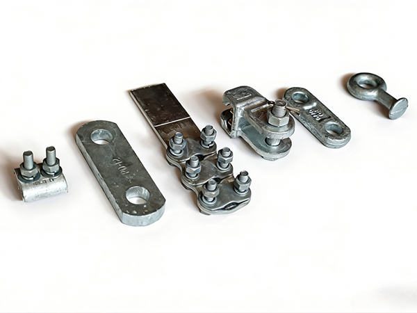
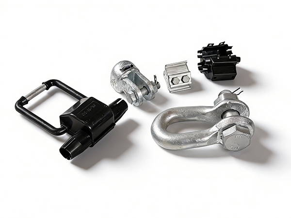
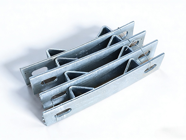
Power hardware components—such as fittings, fasteners, clamps, and connectors—are fundamental to the structural and functional integrity of overhead transmission and distribution systems. Their ability to withstand mechanical loads and environmental stresses must be verified through rigorous strength testing and safety evaluation to ensure reliable long-term operation.
1. Importance of Strength Testing and Safety Evaluation
Strength testing and safety evaluation are essential to:
Verify compliance with design and international standards
Ensure safe load-bearing capacity under normal and extreme conditions
Prevent mechanical failures that could lead to outages or accidents
Improve product quality and lifecycle performance
Testing also provides critical data for design optimization and material selection.
2. Types of Strength Tests
2.1 Tensile Strength Test
This test determines the maximum tensile load a component can withstand before failure:
Conducted using a tensile testing machine
Load is applied gradually until fracture or deformation occurs
Key parameters: Ultimate Tensile Strength (UTS), yield strength, elongation
It is commonly used for bolts, shackles, and tension fittings.
2.2 Compression and Bending Tests
These tests evaluate resistance to compressive forces and bending moments:
Important for components subjected to structural loads
Measures deformation and load-bearing capacity
Helps identify weak points in design
2.3 Shear Strength Test
Shear tests assess the ability of fasteners and connectors to resist sliding forces:
Critical for bolts, pins, and riveted connections
Ensures stability under multi-directional loads
2.4 Fatigue Test
Fatigue testing simulates long-term cyclic loading conditions:
Repeated loading and unloading cycles are applied
Determines fatigue life and crack initiation behavior
Essential for components exposed to wind-induced vibration
2.5 Impact Test
Impact tests evaluate resistance to sudden forces:
Simulates shock loads such as conductor breakage or ice shedding
Measures energy absorption and toughness
Common methods include Charpy or Izod impact testing
3. Environmental and Durability Testing
3.1 Corrosion Resistance Test
Salt spray testing evaluates resistance to corrosive environments
Coating performance (e.g., galvanization) is assessed
Long-term exposure tests simulate real conditions
3.2 Temperature and Thermal Cycling Test
Evaluates performance under extreme temperature variations
Identifies material expansion, contraction, and brittleness issues
3.3 UV and Weathering Test
Important for components with non-metallic parts
Assesses resistance to sunlight, moisture, and aging
4. Safety Evaluation Criteria
4.1 Load Safety Factor
Components must meet required safety factors (typically 2.5–3.0 or higher)
Ensures reliability under unexpected overload conditions
4.2 Failure Mode Analysis
Identifies how and why a component fails
Ensures failure is predictable and non-catastrophic
Helps improve design and material selection
4.3 Structural Integrity
Ensures no cracks, deformation, or defects under working loads
Maintains alignment and load distribution
4.4 Compliance with Standards
Safety evaluation must align with recognized standards such as:
IEC 61284 – Requirements and tests for fittings
ASTM standards for material and mechanical properties
ISO standards for testing procedures
IEEE and ANSI guidelines for power system components
5. Testing Procedures and Quality Control
5.1 Sample Selection
Random sampling from production batches
Representative of actual manufacturing conditions
5.2 Test Conditions
Controlled environment for accurate and repeatable results
Calibration of testing equipment is essential
5.3 Data Recording and Analysis
Record load, deformation, and failure points
Analyze results against design specifications
Maintain traceability for quality assurance
5.4 Acceptance Criteria
Components must meet or exceed specified performance thresholds
Non-conforming products must be rejected or reworked
6. Common Failure Mechanisms
Overload failure: exceeding design load capacity
Fatigue cracking: due to cyclic stress
Corrosion-induced weakening: reducing cross-sectional area
Material defects: inclusions, voids, or improper heat treatment
Improper installation: leading to uneven load distribution
Understanding these mechanisms helps improve both testing and design.
7. Risk Assessment and Safety Improvement
7.1 Risk Identification
Identify critical components and high-risk areas
Evaluate environmental and operational conditions
7.2 Preventive Measures
Use high-quality materials and coatings
Apply proper safety factors
Implement regular inspection and maintenance
7.3 Continuous Improvement
Use test data to refine design and manufacturing processes
Adopt advanced testing technologies and monitoring systems
8. Conclusion
Strength testing and safety evaluation of power hardware components are vital for ensuring the reliability and safety of overhead transmission systems. Through comprehensive testing, strict adherence to standards, and continuous improvement, manufacturers and utilities can minimize failure risks and enhance system performance. A robust evaluation framework not only ensures compliance but also supports long-term operational efficiency and infrastructure resilience.
References
IEC 61284 – Overhead lines – Requirements and tests for fittings
ASTM E8/E8M – Standard Test Methods for Tension Testing of Metallic Materials
ISO 6892-1 – Metallic materials – Tensile testing
IEEE Standard 605 – Guide for Design of Substation Rigid-Bus Structures
ANSI C119 – Electric Connectors Standards
 Recommended Products
 Contact us
—— Contact:Manager
—— Tel:+86 15631793633
—— Email:960244024@qq.com
—— Url:https://www.dachuan-power.com
—— Address:Liugusi Town, Hejian City, Cangzhou City, Hebei Province, China