
NewsDetails
Cracks and Fracture Analysis of Connecting Fittings
author:Dachuan time:2026-04-17 16:08:59 Click:89
Cracks and Fracture Analysis of Connecting Fittings
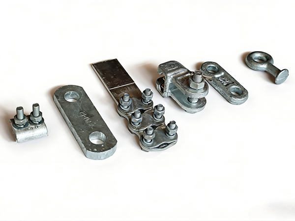
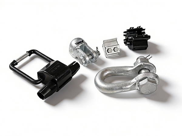
Connecting fittings—such as shackles, yoke plates, clevises, and links—are essential components in overhead transmission and distribution systems. They transfer mechanical loads between conductors, insulators, and supporting structures. Cracks or fractures in these fittings pose a serious threat to system safety, often leading to sudden failure if not detected early. A systematic analysis of causes and appropriate mitigation measures is crucial for reliable operation.
1. Types of Cracks and Fractures
1.1 Surface Cracks
These are visible cracks that appear on the outer surface, often caused by mechanical stress, corrosion, or manufacturing defects. They can propagate inward over time.
1.2 Fatigue Cracks
Develop due to repeated cyclic loading (e.g., wind-induced vibration). Typically initiate at stress concentration points and grow gradually until sudden fracture occurs.
1.3 Brittle Fracture
Occurs without significant deformation, often at low temperatures or due to material defects. This type of failure is sudden and highly dangerous.
1.4 Ductile Fracture
Characterized by noticeable deformation before failure. Usually caused by overload or excessive तनाव beyond material limits.
1.5 Stress Corrosion Cracking (SCC)
Results from the combined effects of tensile stress and a corrosive environment, leading to crack initiation and propagation.
2. Root Causes of Cracking and Fracture
2.1 Material Defects
Impurities, inclusions, or poor metallurgical quality can weaken the structure and create internal stress points where cracks initiate.
2.2 Improper Heat Treatment
Incorrect heat treatment processes can lead to excessive hardness or brittleness, reducing the material’s toughness and resistance to cracking.
2.3 Stress Concentration
Sharp edges, sudden cross-section changes, or poor design create localized high-stress areas that are prone to crack initiation.
2.4 Overloading
Mechanical loads exceeding the rated capacity—due to wind, ice, or improper line design—can cause immediate fracture or accelerate crack growth.
2.5 Corrosion Damage
Corrosion reduces cross-sectional area and introduces pits that act as crack initiation sites.
2.6 Installation Errors
Misalignment, uneven loading, or improper assembly can introduce अतिरिक्त stress, increasing the likelihood of cracking.
2.7 Fatigue from Vibration
Continuous vibration leads to cyclic stress, which gradually weakens the material and causes fatigue cracks.
3. Failure Mechanism Analysis
Crack formation typically follows three stages:
Initiation:
Micro-cracks form at نقاط of stress concentration, corrosion pits, or material defects.Propagation:
Under repeated loading or environmental influence, cracks grow progressively.Final Fracture:
Once the remaining cross-section can no longer تحمل the load, sudden fracture occurs.
Fracture surfaces often reveal important clues:
Smooth, beach-mark patterns indicate fatigue
Rough, fibrous surfaces suggest ductile failure
Flat, shiny surfaces are typical of brittle fracture
4. Detection and Inspection Methods
4.1 Visual Inspection
Useful for identifying surface cracks, deformation, or corrosion.
4.2 Magnetic Particle Testing (MT)
Effective for detecting surface and near-surface cracks in ferromagnetic materials.
4.3 Ultrasonic Testing (UT)
Used to detect internal flaws and crack propagation within the material.
4.4 Dye Penetrant Testing (PT)
Helps reveal fine surface cracks that are not visible to the naked eye.
4.5 Fractographic Analysis
Laboratory analysis of fracture surfaces to determine the exact failure mechanism.
5. On-Site Solutions and Preventive Measures
5.1 Use High-Quality Materials
Select fittings manufactured from high-strength, high-toughness materials with strict quality control.
5.2 Optimize Design
Avoid sharp corners and abrupt section changes. Use smooth transitions to reduce stress concentration.
5.3 Proper Heat Treatment
Ensure appropriate heat treatment processes to balance strength and toughness.
5.4 Corrosion Protection
Apply galvanization or protective coatings to minimize corrosion-related cracking.
5.5 Control Mechanical Loads
Design lines to handle environmental loads such as wind and ice without exceeding fitting capacity.
5.6 Correct Installation Practices
Ensure proper alignment and even load distribution during installation.
5.7 Vibration Mitigation
Install dampers to reduce fatigue caused by wind-induced vibration.
5.8 Regular Inspection and Timely Replacement
Monitor fittings regularly and replace any components showing signs of cracks or damage.
6. Field Troubleshooting Recommendations
If cracks are detected, immediately assess severity and replace the fitting if necessary
If repeated failures occur at the same location, review design and load conditions
If corrosion-related cracks are found, improve protective measures
If fatigue cracks are common, enhance vibration control systems
Conclusion
Cracks and fractures in connecting fittings are often the result of combined effects such as material defects, stress concentration, environmental factors, and cyclic loading. Early detection and proper analysis are key to preventing catastrophic failures. By improving material quality, optimizing design, and implementing effective maintenance strategies, the reliability and lifespan of power line fittings can be significantly enhanced.
References
IEC 61284: Overhead lines – Requirements and tests for fittings
ISO 6892: Metallic materials – Tensile testing
CIGRÉ Technical Brochures on Mechanical Failures of Line Hardware
Electric Power Research Institute (EPRI), Transmission Line Failure Analysis Guide
 Recommended Products
 Contact us
—— Contact:Manager
—— Tel:+86 15631793633
—— Email:960244024@qq.com
—— Url:https://www.dachuan-power.com
—— Address:Liugusi Town, Hejian City, Cangzhou City, Hebei Province, China