
NewsDetails
Cross_Arm_Design_for_Overhead_Power_Lines_A_Practical_Overview
author:Dachuan time:2026-07-01 21:55:34 Click:93
Cross arms have been a fundamental element of overhead power line construction for well over a century. They provide the horizontal support structure that separates conductors at appropriate spacing, supports insulators at the correct angles, and transfers mechanical loads from the conductors and fittings down to the pole. Despite their long history, cross arm design continues to evolve as new materials, improved coatings, and updated loading standards emerge. This article provides a practical overview for engineers and project managers involved in specifying cross arms for distribution and sub-transmission projects.
Role of Cross Arms in Overhead Line Construction
The primary purpose of a cross arm is to hold insulators at a defined distance from the pole and from each other. This spacing determines the electrical clearance requirements for the operating voltage and directly affects safety margins. In wood pole construction, cross arms are typically bolted through the pole at a height that maintains required ground clearance for the lowest conductor. On concrete and steel poles, cross arms may be bolted, clamped, or welded depending on the structural design.
Cross arms also serve as a mounting platform for transformers, cutouts, surge arresters, and other equipment. This multi-functional role means the cross arm must be designed to handle both the dead weight of mounted equipment and dynamic loads from wind, ice, and conductor tension over the entire service life.
Structural Design Considerations
The two most common cross arm profiles are single-arm and double-arm configurations. A single arm extends on one side of the pole and is typically used for lighter loads in 11kV and below systems. Double arms, extending on both sides of the pole, provide symmetric load distribution and are standard for 33kV systems and heavier conductor configurations in the field.
Load calculations follow guidelines established in standards such as ASCE Manual 74 and the applicable national electrical safety codes. Engineers must account for vertical loads from conductor weight plus ice, transverse loads from wind pressure on conductors, and longitudinal loads from unbalanced tension during conductor breakage scenarios. The cross arm must have sufficient section modulus to handle the resulting bending moments without permanent deformation.
Material Choices — Steel Grades and Coatings
Angle steel cross arms are the most widely used type globally, fabricated from hot-rolled angle iron. Q235 steel is the standard grade for most distribution applications, offering a yield strength of approximately 235 MPa. For heavier-duty applications or where weight savings are needed, higher grades like Q345 can be specified by the design engineer.
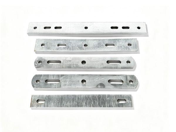
The critical longevity factor is the corrosion protection system. Hot-dip galvanizing per ASTM A123 is the industry benchmark. A properly galvanized cross arm can last 30 to 50 years in most environments before significant rust develops. Some manufacturers also offer zinc-aluminum alloy coatings for enhanced performance in highly corrosive locations such as coastal or industrial zones.
Load Rating and Safety Factors
Every cross arm should be rated for both working load and ultimate load. In most design codes, the working load includes normal service conditions, while the ultimate load covers extreme events such as heavy ice storms or high wind gusts. A safety factor between 2.0 and 2.5 between working and ultimate loads is typical for distribution-class hardware supplied by reputable manufacturers.
Manufacturers should be able to provide test certificates showing that their cross arms meet or exceed these load ratings. Destructive testing of sample cross arms — applying load until failure — is the most reliable verification method available.
Corrosion Protection Through Hot-Dip Galvanizing
Hot-dip galvanizing provides both barrier and sacrificial protection. The zinc coating physically shields the steel from moisture and oxygen, and even if the coating is scratched or damaged, the surrounding zinc continues to protect exposed steel through cathodic action. According to ISO 1461, minimum coating thicknesses range from 45 microns for thin sections up to 85 microns or more for structural steel members exceeding 6mm in thickness.
The quality of galvanizing depends on steel surface preparation, zinc bath temperature control, and immersion time. Manufacturers with in-house galvanizing capability can consistently meet specification requirements and provide traceable quality documentation for each batch.
Manufacturing Capabilities That Matter
When evaluating a cross arm supplier, consider whether the factory offers cutting, drilling, stamping, and galvanizing in an integrated production line. This integration reduces handling damage, shortens lead times, and enables tighter quality control. OEM and ODM capabilities are valuable when non-standard dimensions or configurations are needed for a specific project.
Closing Thoughts
Proper cross arm specification — covering material grade, section size, galvanizing quality, and load rating — is a fundamental step in building a reliable overhead line. Working with a manufacturer who understands these requirements and can provide documented quality assurance helps ensure the infrastructure performs safely throughout its design life.
References
ASCE Manual 74 — Guidelines for Electrical Transmission Line Structural Loading
IEC 60207 — Insulators for Overhead Lines with a Nominal Voltage Above 1000 V
IEEE 751 — Standard for Design Tests for Distribution Transformers
ASTM A123 — Standard Specification for Zinc (Hot-Dip Galvanized) Coatings
We warmly welcome global distributors to partner with us — together we can deliver reliable power line hardware solutions to markets worldwide.
 Recommended Products
 Contact us
—— Contact:Manager
—— Tel:+86 15631793633
—— Email:960244024@qq.com
—— Url:https://www.dachuan-power.com
—— Address:Liugusi Town, Hejian City, Cangzhou City, Hebei Province, China