
NewsDetails
Cross Arm Installation Guide for Power Distribution Lines
author:Dachuan time:2026-06-07 08:32:13 Click:156
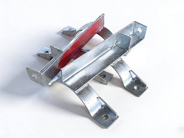
Cross arms provide essential structural support for overhead conductor assemblies, insulator mounting, and equipment attachment on utility poles throughout power distribution networks. These load-bearing components, manufactured by specialized power line hardware suppliers, must sustain vertical conductor weight, horizontal tension forces, and environmental loads including wind pressure and ice accumulation while maintaining dimensional stability over extended service periods. Understanding cross arm structural design, installation procedures, and load capacity evaluation enables construction crews and engineering professionals to ensure safe, code-compliant overhead line installations.
Structural Design and Material Specifications
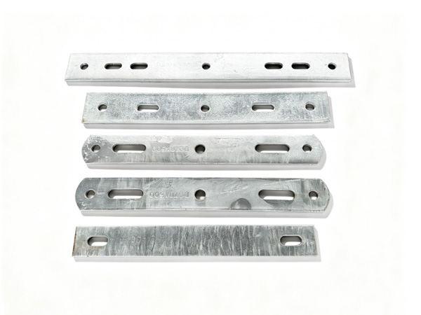
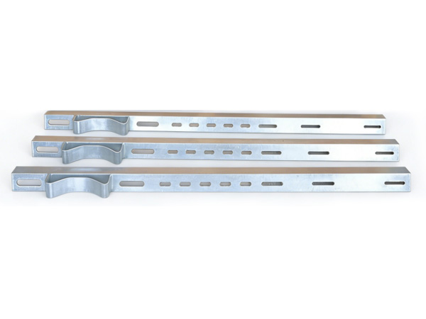
Cross arm structural design incorporates angle steel profiles (typically L75×75×6mm through L125×125×10mm) that provide adequate section modulus and moment capacity for specified loading conditions. Angle steel selection depends on span length, conductor size, loading district (light, medium, or heavy per NESC), and number of conductors supported. Steel grade Q235 provides minimum yield strength of 235 MPa for standard distribution applications, while Q345 grade delivers enhanced capacity for heavy loading conditions.
Hot-dip galvanizing per ISO 1461 applies protective zinc coating (65-85 microns minimum) that prevents base steel corrosion in atmospheric exposure. Galvanizing thickness verification using magnetic thickness gauges ensures coating compliance with specification requirements. Cross arm dimensional tolerances (typically ±2mm for length, ±1mm for hole positions) require precise manufacturing processes including CNC punching and controlled bending operations. Reputable cross arm manufacturers provide dimensional inspection reports and material certification for quality documentation.
Mounting Configurations and Hardware Assembly
Cross arm mounting configurations include single arm, double arm, and bracket-mounted arrangements, each suited for specific structural and electrical clearance requirements. Single arm configurations support standard radial distribution circuits where balanced conductor loading minimizes torsional forces on pole structures. Double arm configurations provide enhanced structural capacity at corner poles, dead-end positions, and long span crossings where unbalanced loading creates significant bending and torsional demands.
Hardware assembly encompasses through bolts, pole clamps, brace assemblies, and insulator mounting hardware that collectively transfer conductor loads from insulator strings through cross arm to pole structure. Bolt grade selection (typically 4.8 or 6.8 property class) provides adequate tensile capacity for connection forces while maintaining ductility to prevent brittle fracture under impact loading. Professional power fitting suppliers provide complete hardware kits with pre-assembled components and installation instructions for field assembly efficiency.
Load Capacity Evaluation and Safety Factors
Cross arm load capacity evaluation considers vertical loading from conductor weight and ice accumulation, longitudinal loading from unbalanced conductor tension, and transverse loading from wind pressure on conductors and arm structure. The combined loading creates bending moment and shear forces that must remain within allowable stress limits with appropriate safety factors (typically 2.0-4.0 depending on application criticality and loading uncertainty).
Deflection limits for cross arms under working loads (typically L/200 to L/360 span ratio) prevent excessive conductor displacement that compromises electrical clearances or creates objectionable visual sag. Cross arm deflection calculations must account for both bending and shear deformation contributions, particularly for short arm configurations where shear deformation becomes significant. Leading cross arm manufacturers provide load capacity tables and deflection curves for standard configurations, enabling rapid selection for common design conditions.
Maintenance Inspection and Replacement Criteria
Cross arm maintenance inspection programs identify corrosion damage, mechanical deformation, connection loosening, and fatigue cracking that compromise structural integrity over service life. Visual inspection protocols assess galvanizing condition (white rust, red rust progression), dimensional distortion (twisting, bending), and fastener condition (corrosion, loosening) at regular intervals. Advanced inspection methods including ultrasonic thickness measurement quantify remaining steel section after corrosion loss.
Replacement criteria establish minimum acceptable conditions for continued service based on remaining structural capacity versus design loading requirements. Galvanizing depletion exceeding 50% of original thickness, steel section loss exceeding 15% of original thickness, or visible cracking in any structural member warrants cross arm replacement. Professional power line hardware suppliers provide inspection training, assessment criteria, and replacement hardware specifications for utility maintenance programs.
References
NESC C2 - National Electrical Safety Code
IEEE C135.1 - Standard for Zinc-Coated Steel Bolts for Overhead Line Construction
ISO 1461 - Hot Dip Galvanized Coatings on Fabricated Iron and Steel Articles
RUS Bulletin 1724E-153 - Guide Specification for Power Line Hardware
ASCE Manual No. 74 - Guidelines for Electrical Transmission Line Structural Loading
 Recommended Products
 Contact us
—— Contact:Manager
—— Tel:+86 15631793633
—— Email:960244024@qq.com
—— Url:https://www.dachuan-power.com
—— Address:Liugusi Town, Hejian City, Cangzhou City, Hebei Province, China