
NewsDetails
Installation Specifications for Electric Power Iron Fittings
author:Dachuan time:2026-04-17 11:30:24 Click:198
Installation Specifications for Electric Power Iron Fittings
Electric power iron fittings (line hardware) are critical components used in overhead transmission and distribution systems to connect, support, and stabilize conductors, insulators, and structural elements. Proper installation ensures mechanical integrity, electrical safety, and long-term reliability. This document outlines standard installation specifications, procedures, and best practices.
1. Scope of Application
These specifications apply to the installation of iron fittings used in:
Overhead transmission lines (35kV–220kV and above)
Distribution lines (≤35kV)
Substation structures and associated hardware
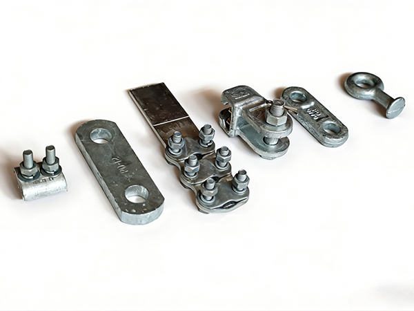
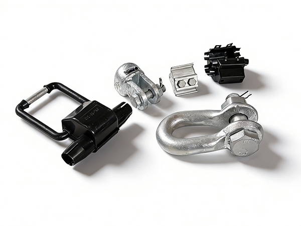
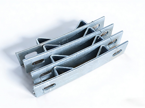
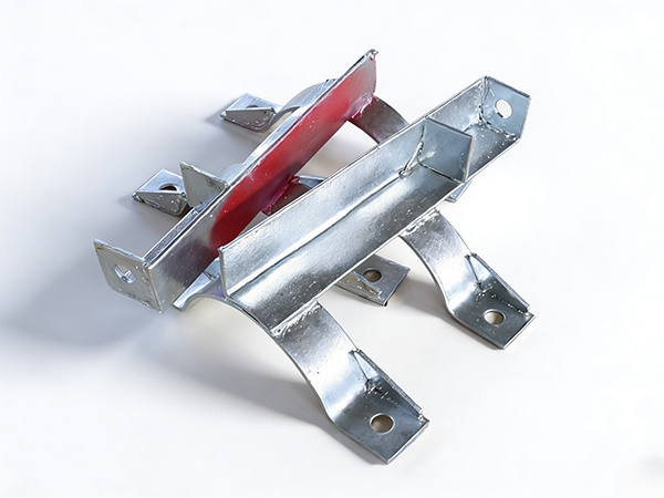
Typical components include suspension clamps, tension clamps, clevises, shackles, bolts, nuts, washers, and fastening accessories.
2. Pre-Installation Requirements
2.1 Material Inspection
Before installation, all fittings must be inspected:
Verify compliance with design drawings and specifications
Check for cracks, deformation, or manufacturing defects
Ensure galvanizing or coating is intact and uniform
Confirm thread quality and dimensional accuracy
Defective components must not be used.
2.2 Documentation and Standards
Review installation drawings and technical specifications
Ensure compliance with applicable standards (IEC, ASTM, ANSI)
Confirm correct component type and rating for the application
2.3 Tools and Equipment
Use calibrated torque wrenches and appropriate installation tools
Prepare lifting and positioning equipment
Ensure availability of safety gear and protective equipment
3. Installation Procedures
3.1 General Assembly Principles
Install fittings according to design orientation and sequence
Ensure proper alignment to avoid eccentric loading
Use compatible components to maintain system integrity
3.2 Fastener Installation
Bolt and Nut Installation
Insert bolts in the specified direction (typically from top to bottom or outside to inside)
Ensure full thread engagement
Use washers where required to distribute load
Tightening Requirements
Tighten fasteners to specified torque values
Avoid over-tightening (risk of damage) and under-tightening (risk of loosening)
Apply uniform torque for multi-bolt connections
3.3 Connection of Fittings
Ensure proper engagement of clevis, shackle, and pin connections
Install cotter pins or locking clips securely
Verify that all movable joints operate freely without binding
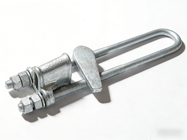
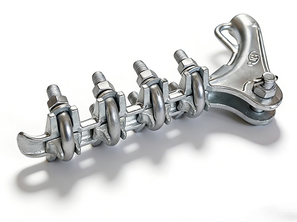
3.4 Installation of Clamps
Suspension Clamps
Position correctly to support conductors without excessive الضغط
Allow limited movement to accommodate thermal expansion
Tension (Dead-End) Clamps
Install at designated locations (angle or terminal points)
Ensure secure gripping of conductors without slippage
3.5 Alignment and Clearance
Maintain required phase-to-phase and phase-to-ground clearances
Ensure correct positioning of fittings relative to insulators and structures
Adjust alignment to ensure even load distribution
4. Quality Control and Inspection
4.1 Visual Inspection
Verify correct assembly and orientation
Check for missing or improperly installed components
Ensure coating integrity (no exposed base metal)
4.2 Torque Verification
Re-check torque values for critical fasteners
Use calibrated tools for accuracy
4.3 Functional Checks
Ensure all articulated components move as designed
Confirm no abnormal stress or interference
5. Safety Requirements
Follow all applicable safety regulations and procedures
Use personal protective equipment (PPE)
Ensure proper grounding and isolation when working near energized lines
Only trained personnel should perform installation
Use certified lifting and climbing equipment
6. Common Installation Issues and Solutions
6.1 Loose Connections
Cause: insufficient torque or missing locking devices
Solution: re-tighten and install proper locking mechanisms
6.2 Misalignment
Cause: improper assembly or structural deviation
Solution: adjust fittings and ensure correct positioning
6.3 Coating Damage
Cause: improper handling or tools
Solution: repair with zinc-rich coating or replace component
6.4 Thread Damage
Cause: cross-threading or contamination
Solution: clean or replace damaged fasteners
7. Post-Installation Requirements
7.1 Final Inspection
Conduct comprehensive inspection after installation
Verify all connections, alignment, and clearances
7.2 Documentation
Record installation details and inspection results
Maintain traceability for future maintenance
7.3 Commissioning Checks
Ensure system readiness before energization
Confirm mechanical stability and electrical safety
8. Maintenance Considerations
Perform periodic inspections for loosening, corrosion, or wear
Re-tighten fasteners if necessary
Replace damaged or degraded components
Maintain records of maintenance activities
9. Conclusion
Proper installation of electric power iron fittings is essential for ensuring the safety, reliability, and longevity of overhead line systems. By adhering to standardized procedures, maintaining strict quality control, and following safety practices, utilities can minimize failure risks and optimize system performance. Careful attention to detail during installation provides a strong foundation for long-term operational success.
References
IEC 61284 – Overhead lines – Requirements and tests for fittings
IEEE Standard 524 – Guide to the Installation of Overhead Transmission Line Conductors
ASTM A153/A153M – Zinc Coating (Hot-Dip) on Iron and Steel Hardware
ISO 898-1 – Mechanical properties of fasteners made of carbon steel and alloy steel
ANSI C135 – Standards for Overhead Line Hardware
 Recommended Products
 Contact us
—— Contact:Manager
—— Tel:+86 15631793633
—— Email:960244024@qq.com
—— Url:https://www.dachuan-power.com
—— Address:Liugusi Town, Hejian City, Cangzhou City, Hebei Province, China