
NewsDetails
Design and Manufacturing Process of Composite Insulators
author:Dachuan time:2026-04-17 16:55:02 Click:112
Design and Manufacturing Process of Composite Insulators
Composite insulators are widely used in modern power transmission systems due to their lightweight structure, strong mechanical performance, and excellent pollution resistance. Their reliability depends heavily on precise design and tightly controlled manufacturing processes. A defect in any stage—material selection, molding, or assembly—can significantly reduce service life and safety performance.
1. Design Considerations of Composite Insulators
1.1 Electrical Design
The electrical design focuses on insulation coordination and creepage distance. Engineers must determine the appropriate:
Rated voltage level (e.g., 110kV, 220kV, 500kV, UHV)
Creepage distance based on pollution level
Shed profile to improve pollution flashover resistance
Hydrophobic silicone rubber surfaces help reduce leakage current and maintain insulation performance even in wet environments.
1.2 Mechanical Design
Mechanical design ensures the insulator can withstand tensile loads from conductors and environmental forces.
Key factors include:
Rated mechanical load (RML)
Safety factor under wind, ice, and vibration conditions
Fiberglass rod diameter and tensile strength
End fitting strength and load transfer efficiency
The fiberglass core is designed as the main load-bearing element, while metal fittings transfer mechanical stress.
1.3 Structural Design
Composite insulators typically use a three-part structure:
Fiberglass epoxy core rod
Silicone rubber or polymer housing
Metal end fittings
The interface between core and fittings must be sealed to prevent moisture ingress, which is critical to avoid brittle fracture failure.
1.4 Environmental Design
Design must account for:
UV radiation exposure
Salt fog and coastal pollution
Industrial chemical environments
Temperature variation and thermal cycling
Different shed shapes and spacing are optimized based on pollution severity.
2. Material Selection
2.1 Fiberglass Core Material
High-strength ECR (Electrical Grade Corrosion Resistant) fiberglass rods are commonly used due to:
High tensile strength
Resistance to stress corrosion cracking
Long-term mechanical stability
2.2 Polymer Housing Material
Silicone rubber is the most widely used material because of:
Hydrophobic surface properties
UV and ozone resistance
Self-cleaning performance under rain
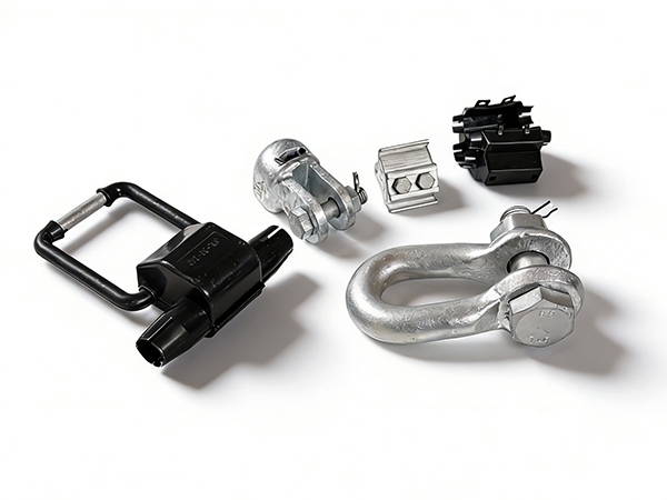
2.3 End Fitting Material
Typically made of:
Hot-dip galvanized forged steel
Aluminum alloy (in some applications)
These fittings must provide high mechanical strength and corrosion resistance.
3. Manufacturing Process of Composite Insulators
3.1 Fiberglass Rod Production
The fiberglass core is produced by:
Impregnating glass fibers with epoxy resin
Pultrusion forming under controlled tension
High-temperature curing to solidify structure
Surface treatment for bonding strength
This process ensures uniform mechanical strength along the rod.
3.2 End Fitting Assembly
Metal end fittings are attached using:
Mechanical crimping
Swaging or hydraulic compression
Adhesive bonding in some designs
Precision is required to ensure tight load transfer without stress concentration.
3.3 Housing (Sheath and Shed) Molding
The silicone rubber housing is formed through:
Injection molding or extrusion molding
High-temperature vulcanization process
Sheds are carefully designed to enhance creepage distance and prevent water film formation.
3.4 Interface Sealing Process
This is one of the most critical steps. The interface between:
Fiberglass rod
Metal end fitting
Silicone housing
is sealed using adhesives or sealing compounds to prevent moisture penetration. Poor sealing can lead to internal degradation and brittle fracture.
3.5 Assembly and Curing
After all components are assembled:
Final curing is performed
Mechanical alignment is checked
Surface defects are inspected
This ensures structural integrity and proper bonding between layers.
4. Quality Control and Testing
4.1 Mechanical Testing
Tensile load test
Bending and torsion resistance test
Proof load verification
4.2 Electrical Testing
Power frequency withstand voltage test
Impulse voltage test
Partial discharge detection
4.3 Environmental Testing
Salt fog test
UV aging test
Thermal cycling test
4.4 Non-Destructive Inspection
X-ray or ultrasonic inspection of core and fittings
Visual inspection for surface defects
Hydrophobicity evaluation
5. Common Manufacturing Challenges
5.1 Poor Interface Sealing
Can lead to moisture ingress and long-term brittle fracture of the fiberglass core.
5.2 Air Voids in Silicone Housing
May cause partial discharge and surface degradation.
5.3 Uneven Fiber Distribution
Reduces mechanical strength and fatigue resistance.
5.4 Improper Crimping of End Fittings
Leads to mechanical loosening or load transfer failure.
6. Process Optimization Strategies
Strict control of raw material quality
Automated pultrusion for consistent fiberglass rods
Precision molding for silicone sheds
Real-time monitoring of curing temperature and pressure
Enhanced sealing and bonding technology
Full batch testing before shipment
Conclusion
The design and manufacturing of composite insulators involve a highly integrated process combining electrical, mechanical, and material engineering. Their performance depends not only on design parameters such as creepage distance and mechanical load rating but also on manufacturing precision, especially interface sealing and material quality control. With strict process management and advanced materials, composite insulators can achieve excellent long-term reliability in diverse and harsh operating environments.
References
IEC 61109: Composite insulators for AC overhead lines
IEC 62217: Polymer insulators for indoor and outdoor use
IEEE Std 1523 – Guide for Application of Composite Insulators
CIGRÉ Technical Brochures on Composite Insulator Design and Manufacturing
Electric Power Research Institute (EPRI), Insulator Production and Reliability Studies
 Recommended Products
 Contact us
—— Contact:Manager
—— Tel:+86 15631793633
—— Email:960244024@qq.com
—— Url:https://www.dachuan-power.com
—— Address:Liugusi Town, Hejian City, Cangzhou City, Hebei Province, China